Engineering · Summer 2024
Sensor Kit.
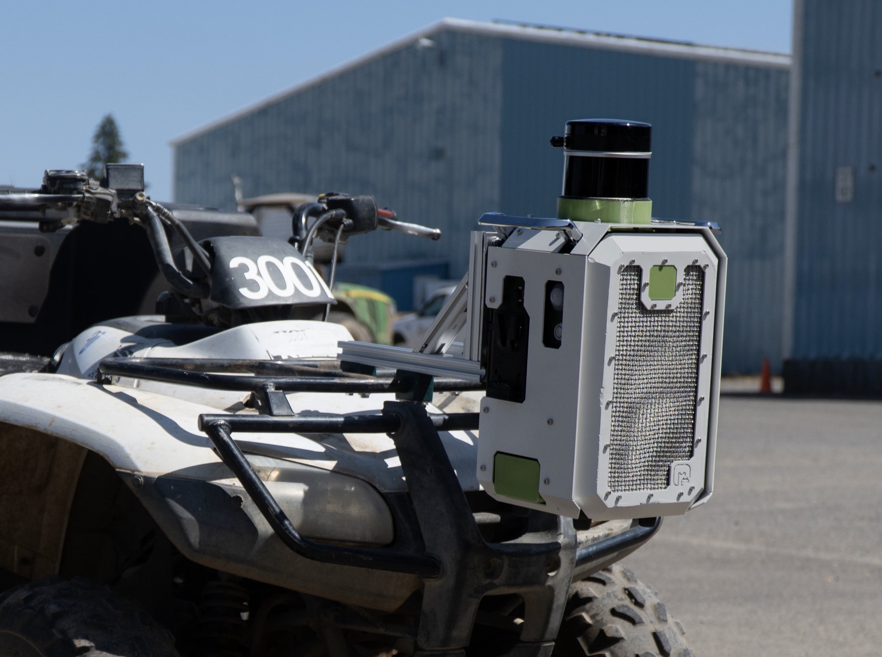
Electrical system for an agricultural robotics sensor kit.
Built the version 2.0 electrical system for the moss sensor kit, an ATV-mounted device that autonomizes tree inventory across farms managing 2 to 10 million trees.
Engineering Intern · Moss · Summer 2024
problem
The problem with manual forestry.
Tree farms run inventory twice a year, minimum. The previous process required 3 people, 2 months, paper records, and manual counting row by row. Version 2.0 of the moss sensor kit replaced that process: mount the box to an ATV, drive the rows, plug in at day's end, and the data appears.
16%
improvement in field accuracy
20%
reduction in sensor failure rates
2–10M
trees per farm
system architecture
How the system is organized.
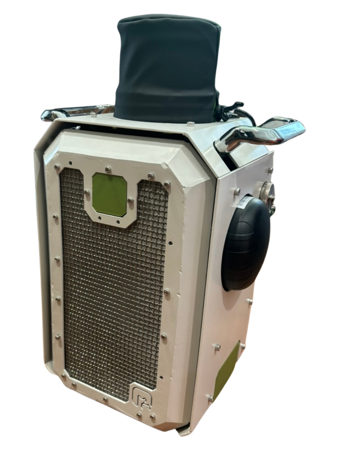
The sensor kit integrates GPS, LiDAR, and IMU data into a single enclosure built for field deployment. Internal architecture is split across three functional zones. All components are wall-mounted to interior enclosure walls and carry IP67 ratings, verified through in-house water testing.
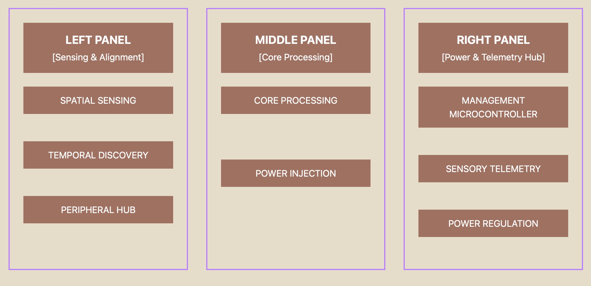
Sensing and Interface Wing
Manages primary spatial sensing arrays and localized data routing infrastructure.
Compute Engine Core
Houses the central high-performance processing node and industrial power injection hardware.
Power and Climate Matrix
Controls environmental monitoring, active thermal regulation, power distribution, and system status indication.
serviceability
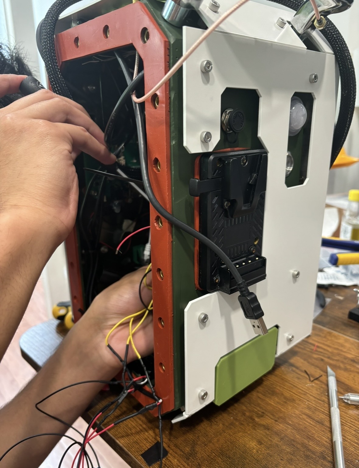
Modular by design.
All components mount to detachable backplanes organized by functional zone. The primary backplate connects to the full power distribution system via a custom Molex connector, allowing the battery and any backplane-mounted component to be swapped in the field without rewiring the main enclosure.
The design came out of an external engineering review: every component required a dedicated mount, a heat sink path, and a fixed position against the enclosure wall. Floating wires and adhesive mounts were eliminated entirely.
manufacturing scalability
Designed to scale beyond one kit per week.
Version 1 was fully hand-wired. One kit took one week to produce, which meant scaling to 10 farms would require 10 weeks of bench wiring with no consistency between units. The solution was two-part: custom PCBs were designed for the time-synchronization subsystem, replacing individual wire runs with a single board, and backplanes were standardized with modular connectors to reduce assembly to a mount-and-connect operation.
A full power budget was mapped per operating state — OFF, IDLE, ACTIVE, COLLECTING — to validate battery capacity and regulation design across worst-case field sessions.
Component wiring map before PCB consolidation
Mid-fidelity cardboard prototype: component placement validation
hardware testing
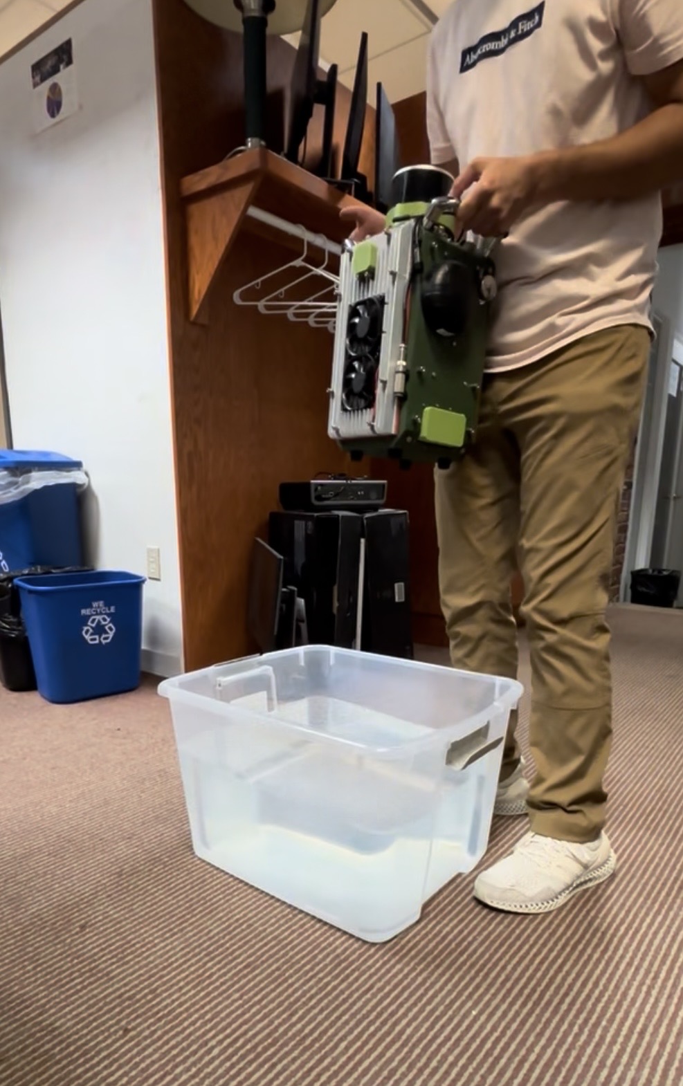
IP67 across every component.
Every component was sourced to meet IP, shock, temperature, and humidity thresholds. No exceptions were made for availability.
Enclosure protection
Target spec
Survive standard Oregon agricultural rainfall
Tested spec
4-hour validation against high-pressure water jets and simulated flooding
outcome
What changed.
What took 3 people 2 months now runs on an ATV. The transition from hand-wired prototype to PCB-driven, backplane-organized assembly created a repeatable manufacturing baseline. Inventory data reaches the office before the sales window closes.